
Images
My first shortwave radio was a Nanaola 10NT504, a receiver that uses superheterodyne technology. In that mode, a radio is tuned by mixing the incoming radio signal with a locally generated variable frequency carrier signal (from a variable frequency oscillator or VFO) in a “mixer” stage, producing two output signals equal to the sum and the difference of the two originals. Those are passed on to a filter tuned to one fixed frequency (often 455 kHz) called the intermediate frequency, which is then amplified, demodulated into audio, amplified again, and sent to a speaker. The VFO signal can be on the high side or the low side of the incoming signal, but in most radios it is on the high side, or 455 kHz + the desired frequency for receiving.
🤖1In a superheterodyne radio using high-side injection, the local oscillator (LO) frequency is set higher than the desired radio frequency (RF) signal. The intermediate frequency (IF) is defined as the difference between the LO and the RF frequencies:
fIF = fLO − fRF
An image frequency is an unwanted signal frequency that, when mixed with the LO, will also produce the same IF and thus could get processed by the receiver unless filtered out. For high-side injection:
- The LO is above the desired RF: fLO = fRF + fIF
Let’s find the image frequency (fIMAGE):
- The mixer responds to both the sum and difference between LO and any incoming signal.
- Any signal at fIMAGE will also appear at IF if:
∣fIMAGE − fLO∣ = fIF
With high-side injection (fLO > fRF), this expands as:
fIMAGE = fLO + fIF
But since fLO = fRF + fIF:
fIMAGE = (fRF + fIF) + fIF = fRF + 2fIF
Therefore, with high-side injection, the image frequency is always equal to the desired frequency plus twice the IF:
fIMAGE = fRF + 2fIF
It is no accident that international broadcast bands are designed to avoid these conflicts as shown in the examples below
| Shortwave Band | Typical Range (MHz) | Image Risk Zone (High-Side, 455 kHz IF) |
|---|---|---|
| 49 meter | 5.9 – 6.2 | 6.81 – 7.11 MHz |
| 41 meter | 7.1 – 7.3 | 8.01 – 8.21 MHz |
| 31 meter | 9.4 – 9.9 | 10.31 – 10.81 MHz |
I once used a Tecsun DR-920 single conversion superheterodyne receiver and I observed images sometimes.

Radio designers use tuned filtering in the input side to reduce images before the IF conversion, and they may use a second conversion stage (dual conversion superheterodyne). In a dual-conversion superhet, a much higher first IF frequency is employed so that the image is far away from the desired signal and easy to filter out, then second IF (typically 455 kHz) is used to increase selectivity. There are even triple conversion superheterodyne radios like the Tecsun PL-880 and PL-990.
Artifacts
Ah, but isn’t all this just ancient history, since radios today are all digital and don’t use mixers and intermediate frequencies? One could hope so, those hopes might be in vain.
A couple of years ago I was tinkering with my XHDATA D-109 receiver with an MLA-30+ antenna, and it received a station that shouldn’t have been there. I did a video about it, assuming that the problem was just overloading, getting a signal too strong for the circuitry.
The D-109 is notorious for overloading from strong local MW broadcast signals, but CHU from Ottawa (the spurious signal) isn’t a strong local broadcast signal, and in fact there are no strong MW broadcast signals where I live.
I got serious after that and used a signal generator to map out where these artifacts are found. The signal generator is analog so I could not make precise measurements of the frequencies:
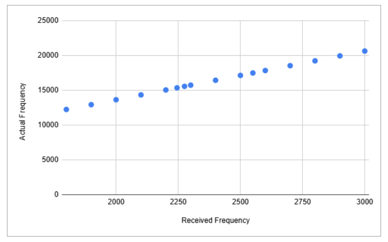
The generator also produces harmonics and there were other spurious hits beyond the ones shown.
Quite a few low-end DSP-based radios don’t even cover the received frequencies in the chart. That’s one way to get rid of artifacts. 😉
I don’t mean to pick on the XHDATA D-109; other DSP radios share a problem picking up a station somewhere on the bands and presenting it on a frequency where it shouldn’t be. I did a video about that some time back involving the Tecsun PL-330, XHDATA D-109, D-808, and the Eton Elite Executive. They all use the Si473x DSP chip series.
🤖DSP Chip Summary2
| Radio Model | DSP Chip Used |
|---|---|
| Tecsun PL-330 | Si4735-D60 |
| XHDATA D-109 | Si4734 |
| XHDATA D-808 | Si4735 |
| Eton Elite Executive | Si4735-D60 |
I also don’t want to pick on Si473x chips. Just this morning I was out at the park testing some radios. Many of my radio tests include something behind the scenes, a Qodosen DX-286 that I use for quick band scans for the purpose of selecting stations to use in the subsequent test, one that may not include the Qodosen radio at all. It uses the TEF6686 DSP chip.
This morning I was using the Sangean ANT-60 antenna with my DX-286 scan. I found two very strong SSB signals, probably from ham operators, on 2395 and 2480 kHz. So I tried them on the radios I was testing (Sangean ATS-909, Tecsun PL-990, Grundig G4000A, Kaito KA1101 and Tecsun PL-660) and those signals simply were not there. They were artifacts. For more on TEF6686 artifacts, see: The Battle of the Sixes: Part 1.
Learn More
If you want to know more about aliasing than I do, check out this article:
What about SDRs?
This is an interesting question. The cause of artifacts in DSP radios comes from under sampling, not accessing the actual signal often enough to get all the necessary information to get it right. Faster sampling requires more compute power. In SDR software, such as SDR++, employing devices like the RTL-SDR Blog V4 dongle, it is possible for the user to set the sampling rate and perhaps deal with these artifacts.
Future Directions
My new signal generator, with digital frequency display and calibrated attenuation, is currently projected to arrive on August 25. When that happens, I can do testing far more efficiently and with greater precision. Also since those YouTube videos above, my number of good radios has greatly increased, both dual-conversion superheterodyne, DSP, SDR and hybrid. I also have a second TEF6686 based radio arriving in September, I hope. There will be all sorts of things to explore.