For some reason the 1985 movie title, Remo Williams: The Adventure Begins, came to mind, perhaps mock titled for a sequel that was never intended to happen. This story keeps on going, and going. In Part 3 episode I track down the EMI emitters (or so I thought).
The first step was to power off the Invisible Fence containment system and disconnect its battery backup. The next step was to verify that the EMI problem continued and to make a quick sweep with a radio to see roughly where it’s heard. Assisting me in this exercise will be my wife who has agreed to flip switches on the electrical panel while I monitor the EMI, using a pair of Baofeng GM-15PRO GMRS 2-way radios (mobile phones are not cool) for communication.
WAIT!
I was all set to tackle the systematic disconnection of circuits in the house, first powering off the containment fence. With the fence was off, unlike last night, EMI wasn’t a problem. The putative second source was silent. CFRX sounded pretty good with my WOW antenna at the radio desk.
So my search is with the Invisible Fence containment system. Unfortunately, the Invisible Fence company doesn’t support their products directly, relying on their independent installers, and the installers are limited in what they know. It looks like my local installer did contact the company to come back with the EMI filter recommendation (the same one I found on the Internet), but that was all. They seem mostly clueless, thinking that there’s nothing odd about a 10.7 kHz signal causing interference on a shortwave radio. “What did you expect, trying to use a radio in the middle of a radio transmitter loop?” While complaints are not widespread, I have found Invisible Fence users having interference on MW radio and around 20 MHz.
I replaced the power supply with no improvement. I’ve added chokes between the power supply and the AC source to no avail. Here’s some video with the radio about 18 ft. from the containment fence transmitter, but near an electrical outlet on the same circuit:

I see that the domain invisiblefencesucks.com is available.
Looking at the problem
I did some more work, digging out my FNIRSI 1014D oscilloscope and hooking it up to the transmitter output to see what’s going on.
Quick tutorial on saving screenshots from the FNIRSI 1014D oscilloscope.
- Locate a cable. A USB-A to USB-A cable (male on both ends) comes with the scope. I used a USB-A to USB-C cable with the A side in the scope and the C side in my computer. Make sure the cable is capable of data transfer and not just charging.
- Save the screenshot by pressing the “S PIC” button. The scope has a 1GB memory, so save as many as you like.
- Press the MENU button and scroll down to the Export USB item (scroll with either the Up/Down buttons or the +/- knob to the left of the OK button and slightly upward.
- Press OK.
- The scope will show an outline image of two devices connected.
- Look at the file manager on your computer and you should see a new drive with .BMP image files. I just use the Windows Photos app to display and then I screenshot them to convert to .PNG.
- Press MENU again to exit Export USB mode.
What I Saw
At a slow scan rate, I could see large spikes on the display:
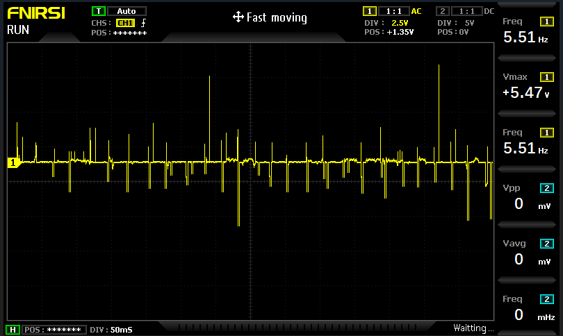
🤖With a timebase of 50 ms/div, we’ve captured a broader window of activity, and the measured 5.51 Hz pulse rate aligns with those intermittent spikes in the video—roughly one burst every 180 ms. That’s right in the range of certain switching power supplies or burst-mode regulators, especially in standby or low-load states.
But look at voltage on that thing, 5.47V max!
At a higher scan rate more detail is shown:
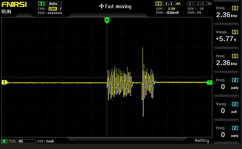
🤖There’s a visible burst of oscillation centered in the screen—likely the “spike” we’re hearing—followed by a flat baseline. That burst appears to have a frequency of about 2.36 kHz, based on the on-screen readout. With a time setting of 1 ms/div, and roughly 10 divisions across the screen, you’re viewing a full 10 ms window. That means the burst spans about 2–3 ms of that window, which fits with what a short electrical transient or EMI pulse might look like.
Next Step
I’ve been putting it off for 4 months, installing the EMI filter between the transmitter and the containment loop. I put it off because it’s going to require mounting something to the wall and the space around the transmitter is cramped. Nevertheless, having exhausted every other option, this is all that’s left, and so I’ll do it.
I installed the filter. The result was a reduction in EMI going to the containment field loop, as can be seen with the new scope result:

Yes, there is attenuation, but there’s still lots of noise, and it did nothing to reduce the EMI going into the house.
So that leaves the extreme solution: trashing the entire system and putting something in from another brand.